
Why Choose Precision Optical Components Machining?

Time:2026-10-30 Author:Mason
0%

Why choose precision optical components machining? Because a lens or mirror must do more than look smooth. It must guide light predictably. Optical Components Machining controls geometry, surface finish, and alignment across each production stage. A small error can shift a focal point, soften an image, or reduce throughput. Details matter. A polished surface can still fail if its shape is wrong.

James C. Wyant, an optical metrology expert, has advanced the measurement methods used to evaluate optical surfaces. A practical paraphrase of that metrology principle is: “Precision matters only when it can be measured and verified.” That idea connects machining with inspection, from tool selection to final surface testing. Skilled teams track material behavior, machining forces, and temperature changes. They may inspect a component between operations, not only at the end. The process can be demanding. It is also not perfect: measurement limits, setup errors, and material variation can leave uncertainty. A reliable supplier explains those limits instead of promising flawless results. For engineers choosing a machining partner, that candor matters alongside equipment, documented inspection, and repeatable results. The right process turns tight specifications into dependable optical performance.
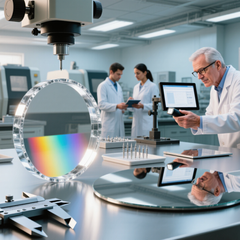
Why Choose Precision Optical Components Machining?

What Precision Optical Components Machining Involves

Precision optical components machining shapes lenses, mirrors, prisms, and other parts to control how light travels. The process starts with a suitable optical material and a drawing that defines dimensions, surface quality, and alignment requirements. Operators may use precision grinding to establish the component’s shape, followed by polishing to reduce surface irregularities. Small errors matter. A slight wedge or off-center curve can shift a beam or blur an image.

Machining is only part of the work. Technicians check dimensions, surface finish, and optical performance using suitable measurement tools, such as profilometers or interferometers. They also consider how the part will be mounted and handled. A lens may meet its surface specification yet perform poorly if its edges or alignment are overlooked. This is easy to miss, even in a careful workflow. Inspection plans should match the component’s material, geometry, and intended use.

Tips: Confirm critical dimensions and inspection methods before production. Keep optical surfaces clean, and handle parts with appropriate gloves. Allow time for rework; tight tolerances can make a simple-looking part unexpectedly difficult.

How Machining Processes Shape Optical Performance

Machining determines more than an optical component’s shape. It influences how light reflects, refracts, and travels through the finished part. A slight radius error can shift a focal point, while surface waviness may scatter light and reduce image contrast. Small errors matter.

The process must suit the material and optical function. Grinding removes material efficiently, but it can leave subsurface damage that later polishing must address. Diamond turning can produce precise curved surfaces, though tool marks may affect performance in some applications. Heat changes things. Cutting speed, tool condition, and fixture pressure can all influence the result, so process settings need careful control.

Measurements connect the machining plan to actual performance. Interferometry can reveal surface deviations; profilometry helps assess roughness at a smaller scale. These readings are useful, but they do not tell the whole story unless testing reflects the component’s intended use. A lens may meet its surface specification and still perform poorly after assembly. That is an easy detail to overlook. Designers and machinists should review tolerances together, especially when coatings, mounting stress, or temperature changes could alter the optical path. There is rarely one perfect route; sometimes the practical choice needs another test.

Why Choose Precision Optical Components Machining?

How Surface Finish Can Shape Optical Performance

For an ideal smooth surface at normal incidence, estimated total integrated scatter rises approximately with the square of RMS roughness. These values use the smooth-surface approximation TIS ≈ (4πσ/λ)² at a wavelength of 550 nm. They are theoretical estimates, not measurements; actual performance also depends on factors such as surface defects, coatings, and roughness spatial frequency.

Materials and Tolerances Used in Optical Component Production

Optical component materials determine more than refractive power. They also affect thermal stability, polishability, and machining risk. Fused silica is a common choice for demanding thermal environments, while calcium fluoride suits applications requiring ultraviolet transmission. Malitson’s 1965 Journal of the Optical Society of America measurements report fused silica’s refractive index as 1.45846 at 589.3 nm. That precise value helps designers predict how a lens bends light. Small differences matter.

Tolerances must match the optical function, not just the drawing’s appearance. ISO 10110-5 specifies how surface-form tolerances are represented, while ISO 10110-7 addresses surface imperfections. For a high-performance polished surface, a specification near λ/10 peak-to-valley may be appropriate; it is not a universal requirement. A shop may also control centering, wedge, and edge thickness to hundredths of a millimeter, depending on the part. Check the measurement method, too. A tolerance without a defined inspection method can invite disagreement. One often-overlooked detail is material stress: a clear blank can still distort the wavefront after machining. That deserves a second look.

Why Choose Precision Optical Components Machining? — Materials and Tolerances Used in Optical Component Production

Optical Material Relevant Material Properties Common Component Uses Typical Finished-Part Dimensional Tolerance Typical Optical Surface Targets Production Considerations
Optical glass Available in many refractive-index and dispersion ranges; suitable for visible and near-infrared optics. Lenses, prisms, windows, and mirrors Diameter or length: about ±0.02–0.05 mm; thickness: about ±0.02–0.05 mm Polished surface roughness commonly around 0.5–2 nm RMS; surface figure may be specified from λ/4 to λ/10 at 632.8 nm. Glass type, part size, edge geometry, and polishing method affect achievable results.
Fused silica Low thermal expansion and good transmission over a broad spectral range, including ultraviolet wavelengths. Laser windows, UV optics, precision lenses, and reference flats Diameter or length: about ±0.02–0.05 mm; thickness: about ±0.02–0.05 mm Polished surface roughness commonly around 0.5–2 nm RMS; tighter figure requirements may be specified for precision optics. Its low thermal expansion is useful where temperature stability matters; UV transmission depends on material grade and wavelength.
Sapphire High hardness, high strength, and good transmission across portions of the visible and infrared spectrum. Protective windows, watch-cover optics, and demanding inspection windows Diameter or length: about ±0.03–0.10 mm; thickness: about ±0.02–0.05 mm Optical polishing can achieve low-nanometre RMS roughness; figure requirements depend on aperture and application. High hardness can increase grinding and finishing time; edge chips and subsurface damage require careful control.
Calcium fluoride (CaF2) Broad ultraviolet-to-infrared transmission and relatively low refractive index; comparatively soft and brittle. UV and infrared lenses, spectrometer optics, and windows Diameter or length: about ±0.03–0.10 mm; thickness: about ±0.03–0.08 mm Polished roughness and figure are specified for the wavelength and application; handling and finishing limits may govern the achievable target. Its fragility calls for conservative fixturing, edge handling, and polishing conditions.
Zinc selenide (ZnSe) High infrared transmission over useful wavelength bands; relatively soft compared with many optical glasses. Infrared lenses, laser optics, and thermal-imaging windows Diameter or length: about ±0.03–0.10 mm; thickness: about ±0.03–0.08 mm Surface finish and figure are set by the wavelength, coating, and system performance requirements. Protect surfaces from scratches and follow appropriate controls for material dust and handling.
Silicon Useful infrared optical material with good thermal conductivity; opaque in the visible range. Infrared windows, mirrors, and semiconductor-related optical parts Diameter or length: about ±0.02–0.05 mm; thickness: about ±0.02–0.05 mm Surface figure and finish depend on whether the part is polished, ground, or used as a reflective surface. Crystal orientation, surface condition, and thermal or mechanical requirements should be included in the drawing specification.

Tolerance ranges are illustrative engineering values, not guaranteed specifications. Actual capability depends on part size and geometry, material grade, machining and polishing route, inspection method, and order quantity. Define surface figure, roughness, centering, wedge, and edge requirements on the part drawing when they are critical.

Benefits of Precision Machining for Optical Systems

Precision machining gives optical assemblies repeatable geometry. Lens seats, mirror cells, and alignment datums can be cut to controlled dimensions. This helps reduce tilt, decenter, and mounting stress. Small errors matter.

A precisely machined mount can keep a lens centered without uneven clamping. Consistent production also helps when replacement parts must fit without a full optical realignment. But machining marks still need suitable finishing. Cutting alone rarely produces the final optical figure or low-scatter surface.

NASA’s Webb telescope technical documentation describes 18 primary-mirror segments, each 1.32 meters across, with surface accuracy around 20 nanometers. This benchmark depends on a complete fabrication and verification chain, not machining alone.

Precision machining helps by stabilizing interfaces, thickness, and reference surfaces before polishing, coating, and metrology. Yet tighter tolerances increase inspection time and cost. They may also be wasted if thermal drift or mounting forces dominate. Each tolerance should serve a measurable optical requirement and be checked under realistic operating conditions.

Factors to Consider When Choosing a Machining Provider

Why Choose Precision Optical Components Machining? Factors to Consider When Choosing a Machining Provider

Choosing a machining provider means looking beyond advertised tolerances. Ask how they control lens seats, bore alignment, and surface finish across production runs. A small centering error can shift an optical axis; a rough contact surface may complicate assembly. Request sample inspection records and learn which measuring tools verify critical features. Experience with your material matters, too, since glass, aluminum, and technical plastics respond differently to cutting and handling.

Discuss the full process, from drawing review to final inspection. A capable provider should flag unclear dimensions, explain achievable tolerances, and describe how parts are protected from scratches and contamination. Ask about prototype changes, batch consistency, and nonconformance handling. A polished capability sheet is not proof. Review actual documentation where possible. Even a well-equipped shop may need a trial run to settle a demanding design, and that can reveal issues early.

Tips: Share a clearly marked drawing and identify critical-to-function dimensions. Ask for a first-article report, including how measurements were taken. Compare quotes for inspection scope, lead time, and communication—not price alone. If an answer feels vague, ask for a concrete example.

FAQS

What does precision optical component machining involve?

It shapes lenses, mirrors, prisms, and related parts. Grinding establishes the form, while polishing reduces surface irregularities. Small errors matter.

How can machining affect optical performance?

A slight radius error can shift a focal point. Surface waviness may scatter light and reduce image contrast. Tool marks can matter too.

Which measurements help check an optical part?

Interferometers can reveal surface deviations. Profilometers assess fine roughness. Measurements should match the part’s material, shape, and intended use.

Why do material and machining choices matter?

Grinding removes material efficiently, but may leave subsurface damage. Diamond turning can create curved surfaces, though tool marks may affect performance.

How does precision machining help optical assemblies?

Accurate lens seats and mirror mounts can reduce tilt, decenter, and uneven clamping. This may also simplify replacement without full realignment.

Is machining alone enough to produce a finished optical surface?

Usually not. Cutting often needs further polishing and inspection. A part can meet its surface specification and still perform poorly after assembly.

Why should tolerances reflect real operating conditions?

Very tight tolerances raise inspection time and cost. Temperature changes or mounting forces may dominate. Some details are easy to overlook.

What should teams confirm before production?

Agree on critical dimensions and inspection methods. Keep optical surfaces clean, handle parts with suitable gloves, and allow time for rework. A simple-looking part may not be simple.

Conclusion

Precision Optical Components Machining is the controlled production of optical parts to meet demanding requirements for shape, surface quality, and dimensional accuracy. Processes such as precision milling, turning, grinding, and polishing help define how light passes through or reflects from a component, influencing focus, alignment, and overall system performance. The right process depends on the part’s design, intended optical function, and production needs.

Materials may include optical glass, crystals, ceramics, or engineered polymers, each requiring suitable machining methods and carefully managed tolerances. Precision machining can support consistent quality, reliable assembly, and complex geometries while reducing unwanted variation across components. When choosing a machining provider, consider its process capabilities, material experience, inspection methods, tolerance control, communication, and ability to meet project schedules. Matching these factors to the optical system’s requirements helps ensure that components perform as intended.

Mason

Mason

Mason is a seasoned marketing professional with a deep expertise in the company's offerings and a passion for driving brand awareness. With a strong background in digital marketing strategies, he has an innate ability to connect with diverse audiences and effectively communicate product benefits.......