ODM Custom CNC Turned Contact Pins & Test Probe Components Manufacturer, Exporters

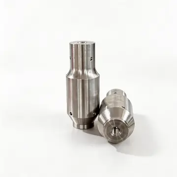
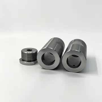
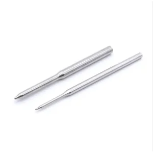
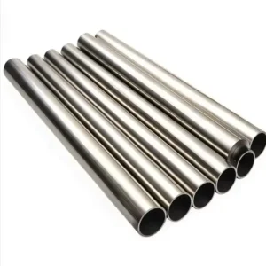
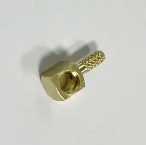
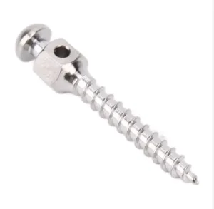
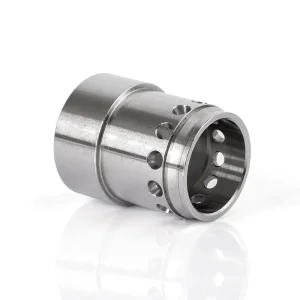
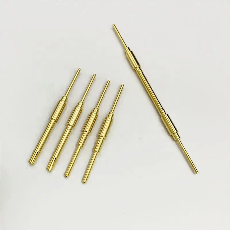
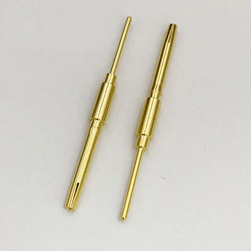
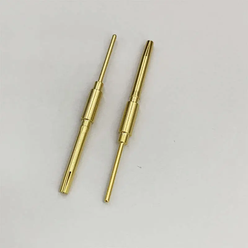
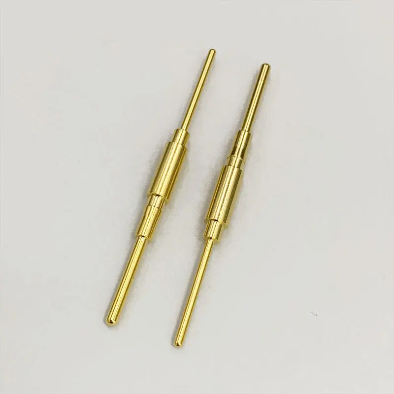
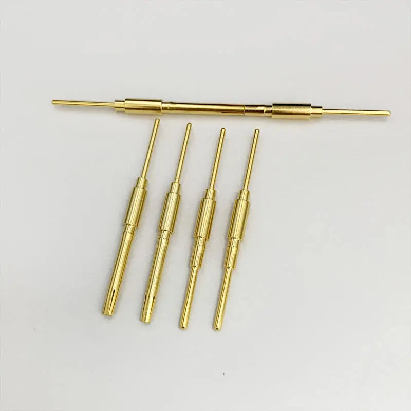
Match the contact to your test fixture, not your fixture to a catalog pin. Shenzhen Sunmy Hardware Co., Ltd. manufactures custom CNC-turned contact pins, plungers, stepped barrels and slotted receiver sockets from customer drawings or samples. Pin length, mating diameter, bore, collar positions, tip form and plating are tailored to your connector or electrical test fixture.

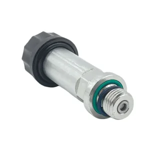
We can supply individual machined components or review a complete probe assembly against your drawing. Springs, receptacles and assembly testing are included only when listed in the quotation. High-current and spring-loaded applications require an agreed operating specification and validation plan; the pictured geometries do not establish an electrical rating or service life.

Product Description

Product Overview

Match the contact to your test fixture, not your fixture to a catalog pin. Shenzhen Sunmy Hardware Co., Ltd. manufactures custom CNC-turned contact pins, plungers, stepped barrels and slotted receiver sockets from customer drawings or samples. Pin length, mating diameter, bore, collar positions, tip form and plating are tailored to your connector or electrical test fixture.

We can supply individual machined components or review a complete probe assembly against your drawing. Springs, receptacles and assembly testing are included only when listed in the quotation. High-current and spring-loaded applications require an agreed operating specification and validation plan; the pictured geometries do not establish an electrical rating or service life.

Manufacturing & Process Insights

The manufacturing route is selected around the drawing, alloy, finished fit and order volume. CNC turning or Swiss-type machining can be combined with bore machining, longitudinal slotting, heat treatment and plating as the component requires:

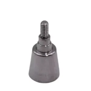
CNC Turning & Datum Control: Machine stepped diameters, locating collars and contact tips from agreed reference features. Select workholding and any secondary setups to suit slender sections, length and the specified axis-alignment requirements.
Micro-Drilling & Bore Finishing: Review bore diameter, depth, wall thickness and tool access together. Define finish requirements on the functional bore; confirm sliding or mating fit after the specified surface treatment.
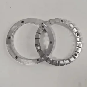
Longitudinal Slotting & Slitting: Produce slots and contact fingers to the approved width, length, root geometry and orientation. Define edge-break and burr limits without assuming that every slotted tube has the same retention or contact function.
Deburring, Cleaning & Heat Treatment: Select cleaning and deburring methods that preserve thin walls and contact edges. Apply age hardening or stress relief only where appropriate to the specified alloy, condition and finished-part requirements.
Controlled Contact Plating: Specify gold or silver finish, nickel underplate, thickness and functional coverage separately. Confirm plating access to recessed features and inspection locations; hard gold and soft gold are not interchangeable specifications.

Key Specifications & Engineering Customization Scope

The dimensions and processing targets below are references for quotation review, not verified specifications of the pictured parts or a fixed catalog range. Final limits depend on geometry, material and finish; listed extremes are not assumed achievable together.

Specification Parameter Customization Options & Review Requirements
Manufacturing Process CNC turning / Swiss-type turning, drilling, boring and secondary slotting. Process and fixture strategy confirmed for each drawing.
Base Material Options • Brass: C3604, C3602 or C36000
• Beryllium copper: C17300 or C17200
• Phosphor bronze C5191; tellurium copper C14500
• Stainless steel: SUS303, SUS304 or SUS316
Specify the exact grade, material standard and temper.
Dimensional Range • Reference OD: 0.4–12.0 mm; length: 2.0–80.0 mm
• Thin-wall target: 0.08 mm, subject to geometry review
Custom sizes and proportions assessed from your drawing.
Machining Tolerances • Reference OD target: ±0.005 mm; length: ±0.01 mm
• Axis-alignment target: 0.01 mm, with datum and tolerance type defined on the drawing
Specify finished dimensions and plating allowances.
Internal Bore & Slotting • Bore diameter from 0.3 mm for feasibility review; specify depth and wall thickness
• Two-slot, four-slot and other socket geometries to drawing; slot roots and edge limits defined separately
Surface Roughness • Reference external finish: Ra 0.2–0.8 µm
• Functional bore target: Ra ≤ 0.4 µm, subject to access
Define measurement location and before/after-plating condition.
Surface Finishing & Plating • Gold options for review: 0.5, 3, 5, 10, 20 or 50 µin
• Silver: 3–10 µm reference; nickel underplate: 50–100 µin
• Specify gold type and electroplated or electroless nickel separately, plus coverage and acceptance criteria
1 µin = 0.0254 µm. Compliance documentation by project.
Heat Treatment Options Age hardening for appropriate BeCu grades; other treatments per alloy and drawing. Specify final material condition, hardness scale, test load and inspection location.
Electrical & Contact Performance No universal current, resistance or cycle-life rating. Define continuous/peak current, duty cycle, temperature, mating part and contact force; include working stroke for spring-loaded assemblies. Validate the agreed configuration.
Quality Assurance & Inspection Optical dimensional checks, suitable gauges and XRF coating checks at specified accessible locations. Sampling, full inspection, force/resistance tests and salt-spray conditions agreed in the inspection plan.
Packaging Method Protective trays, bags or bulk packing selected to protect tips, slots and plating. Tape-and-reel and ESD packaging available for review against the part geometry and handling requirements.

Key Advantages & OEM Value Proposition

Geometry Built Around Your Interface: Customize contact tips, collars, bores and slots together. Provide the mating part so the manufacturing review addresses the assembled fit, not just a list of separate dimensions.
Finished Fits, Not Bare-Metal Dimensions: Define working diameters, bore clearance and edge condition after plating. Align the machining allowance and inspection plan with the coating specified for your contact surfaces.
Plating Where the Contact Needs It: Review functional zones, coating type and thickness before quotation. Compare cost and inspection requirements without treating gold color or a thicker coating as a current or lifetime guarantee.
Prototype-to-Production Coordination: Resolve material, tooling access and finishing questions before samples. Approve the drawing revision, prototype scope and delivery schedule, then plan repeat orders around the accepted configuration.
Documented Acceptance Requirements: Request dimensional, material and coating records in the RFQ. Agree traceability, sampling and any assembly tests up front so the quotation includes the evidence your incoming inspection needs.

Other Products

Technical FAQ for Global OEM Buyers

Q1: How are material, plating and heat-treatment requirements verified?
Agree the inspection plan before production. XRF checks use suitable calibration and defined accessible locations; inaccessible internal coatings require an agreed alternative verification method. Specify supplier material records, including EN 10204 3.1 where applicable and available. Heat-treatment verification uses the specified hardness method and test load; HV results are not automatically HRC results.
Q2: Can you customize the bore, wall thickness, slots and contact tip?
Yes. We review complete custom geometries from 2D/3D drawings or samples, including stepped bores, split sockets, collars and round, spear, concave, serrated or flat tips. The 0.3 mm bore and 0.08 mm wall references require separate feasibility review. Final limits depend on bore depth, material, slot geometry, plating and inspection access.
Q3: How are current, contact resistance and mating life specified?
Set acceptance requirements for the complete contact configuration. Define the mating surface, force, working stroke where relevant, temperature, current duty and failure criteria. Four-wire resistance measurements, temperature-rise evaluation and cycle testing address different requirements and are included only as agreed. A dimensional or plating report alone does not qualify an assembled probe for high-current service.
Q4: What are the MOQ and lead times for a custom project?
Prototype and production quantities are reviewed separately; no fixed catalog MOQ limits your enquiry. Reference schedules are 3–5 working days for straightforward machined samples and 10–14 days for repeat production, subject to material, finishing, testing and available capacity. Confirm the complete scope in the quotation; blanket orders and buffer stock can be discussed. Send your 2D drawing, 3D model or sample details, mating-part requirements, material and plating specification, quantities and target delivery date. We will review the manufacturing route and prepare a project-specific quotation.
Q5: What base materials and contact plating finishes can be specified?
We machine various alloys including Brass (C3604, C3602, C36000), Beryllium Copper (C17300, C17200), Phosphor Bronze (C5191), Tellurium Copper (C14500), and Stainless Steel (SUS303, SUS304, SUS316). Plating options cover selective or overall gold (0.5 to 50 µin) and silver (3–10 µm) with electroless or electrolytic nickel underplates (50–100 µin), fully verified per project specifications.
Q6: How is tolerance stack-up and finished-fit managed after surface plating?
Finished dimensions and mating tolerances (such as our reference OD target of ±0.005 mm and length target of ±0.01 mm) account for coating build-up. We align secondary machining allowances, axis-alignment targets, and optical inspection checks directly with your post-plating specifications to prevent tight-bore interference and interface binding.

Get a Fast, Technical Quote & Free DFM Review

Don't let tolerance stack-up delay your product launch. Submit your project details, and our engineering team will evaluate your design for manufacturability before the first cut.
Related Products