China Custom 6-Axis Force/Torque Sensor Housings & Elastic Elements | OEM/ODM Service, Factories
Product Description
Product Overview
Built around the mechanical requirements of six-axis force/torque (F/T) sensing, these custom cylindrical housings, mounting flanges and elastic elements are manufactured for sensor developers, robot integrators and automation OEMs. Their mechanical interfaces can be designed for Fx, Fy, Fz and Mx, My, Mz sensing architectures; measurement accuracy depends on the completed sensor design, instrumentation and calibration.
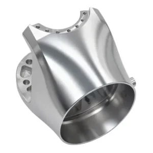
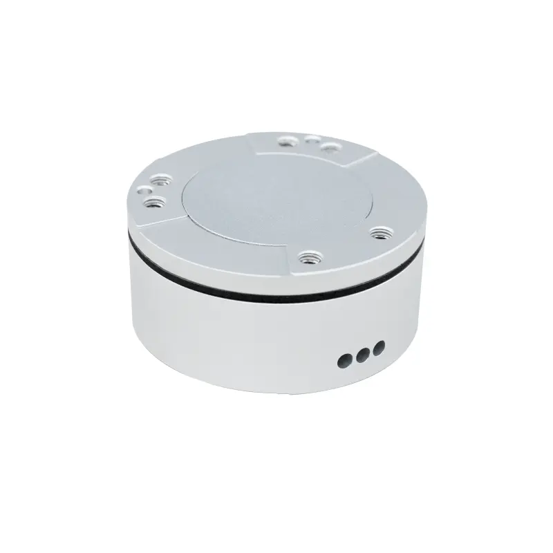
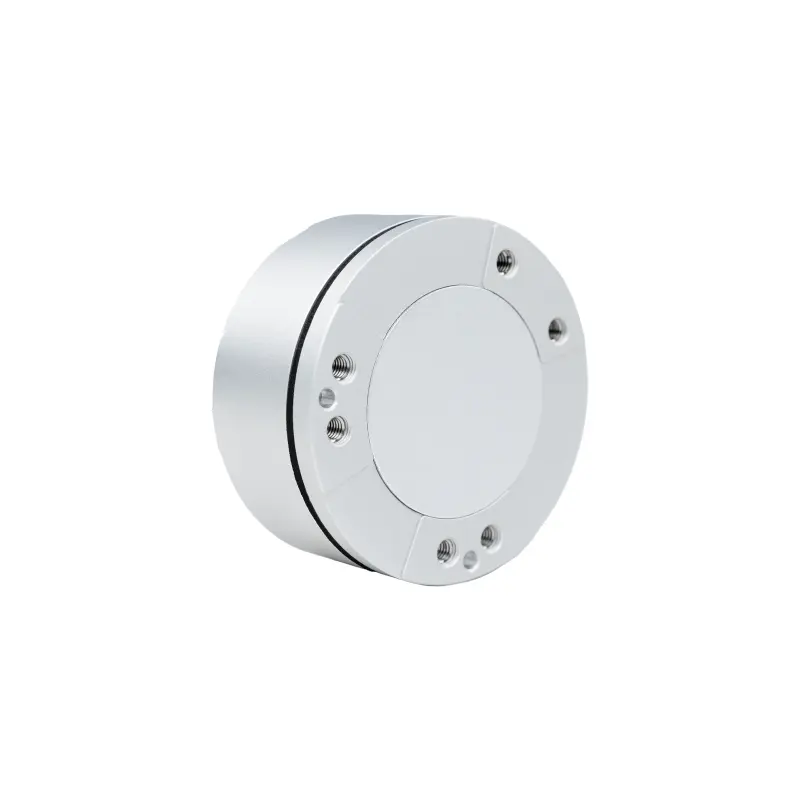
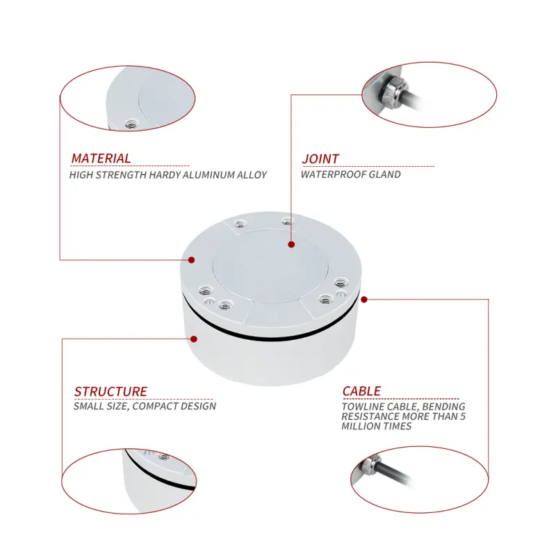
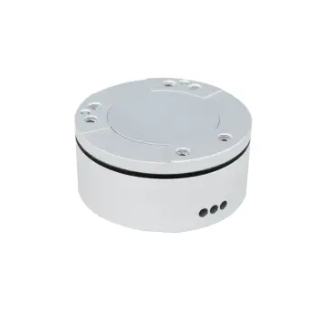
The reference features a compact circular body, a recessed top face, mounting holes and a circumferential joint. Sunmy Hardware builds mechanical parts to customer drawings or samples, with optional support for matching brackets, turned parts, inserts and defined subassembly work. Electronics, protocols, sealing ratings and calibrated sensor performance are project-specific and must be verified separately.
Manufacturing Process & Craftsmanship Insights
Six-axis sensing structures demand careful treatment of mounting datums, wall thickness, elastic-zone geometry and residual stresses. Manufacturing and inspection routes are selected directly from the approved 2D/3D design, rather than assigning a fixed sensor performance claim to an unfinished mechanical component:
Machine cylindrical housings, mounting flanges, stepped bores and threaded patterns from approved aluminum or stainless steel grades. For elastic elements, tool access, datum control and material condition are reviewed against the specified load path.
Use suitable precision milling, drilling or specialist EDM processes where the drawing requires fine slots or compliant features. Deburring, fixturing and any post-machining stress-relief treatment are defined for the chosen alloy and dimensional requirements.
Offer machined, bead-blasted, anodized or other specified finishes where material-compatible. Mask critical contact areas and confirm finished dimensions, surface condition and any coating effects on assembled interfaces.
Coordinate threaded inserts, covers, sealing features, mounting hardware and assembly as required. Review fit with mating components and inspect agreed critical dimensions using suitable gauges, optical measurement or CMM. Strain gauges, PCBA, multi-axis calibration and IP testing require a separately agreed scope and qualified verification.
Key Technical Specifications
The following are engineering quotation options for custom mechanical parts, not certified specifications of a completed force/torque sensor. Final values and verification methods are agreed from the customer drawing, BOM and application requirements:
| Parameter | Mechanical Component Scope | OEM / ODM Options |
|---|---|---|
| Product Type | Custom F/T sensor housing, flange and elastic element | Part-level manufacturing or agreed subassembly |
| Sensing Application | Mechanical interfaces for 6-axis F/T systems | Designed around customer load paths and datums |
| Force Range (Fx, Fy, Fz) | Determined by the complete sensor design | 50–200 N may be a project reference, not a rating |
| Torque Range (Mx, My, Mz) | Determined by the complete sensor design | Torque limits assessed with customer engineering team |
| Mechanical Tolerances | Feature-specific GD&T per approved 2D drawing | Tighter features subject to feasibility and inspection |
| Sensor Accuracy / Calibration | Not defined by the mechanical housing alone | Electronics and calibration agreed separately |
| Overload Requirements | Defined by elastic geometry and system architecture | Mechanical stops reviewed if included in design |
| Outer Diameter & Height | Built to print; compact circular form shown | Custom OD, height and mounting pattern |
| Housing & Elastic Materials | 6061/7075 aluminum or stainless steel, as specified | 17-4PH or titanium assessed on request |
| Mechanical Mounting | Threaded holes, locating features and flange interfaces | Customer bolt patterns; ISO 9409-1 if specified |
| Electronics & Protocols | Outside standard machined-part supply | Integration evaluated against supplied BOM |
| Electrical Supply | Defined by selected electronics and sensor architecture | Wiring provisions only if specified |
| Sealing / IP Performance | No default IP rating from housing appearance | Gland, gasket and IP tests if specified |
| Cable & Connector | Cable passages and connector-mount features by drawing | Specified glands, connectors or prepared assembly |
Key Features & Competitive Advantages
-
Precision Mechanical Interfaces: Custom holes, locating surfaces, shallow grooves and stepped sections are designed for the mating robot flange or sensor stack, with critical fit features identified during DFM.
-
Application-Specific Elastic Geometry: For a customer-supplied elastic-element design, machining sequences and fixturing are assessed to help control dimensional variation. Sensor-level sensitivity, overload and cross-talk remain subject to finished-system validation.
-
Finish & Assembly Compatibility: Surface treatments, covers, fasteners and cable-entry details can be coordinated in one BOM. Sealing performance and electrical interfaces are not assumed without project testing.
-
Fully Custom, Drawing-Led Development: Send 2D/3D files or a sample for DFM feedback on geometry, material, installation footprint, tolerances and cost-sensitive features. Prototype quantities and manufacturing routes are flexible.
-
Multi-Process Supply & Mechanical Assembly: Sunmy coordinates CNC machining, turning, casting, stamping, injection molding, finishing and agreed assembly steps. We can supply matched mechanical parts or inspected mechanical subassemblies to simplify purchasing and fit checks.
Other Products
Technical Frequently Asked Questions (FAQ)
Q1: Can you manufacture sensor housings and elastic elements for our robot interface?
A: Yes. We make custom mechanical components from approved drawings, including mounting hole patterns, circular housings, flanges and specified elastic-element geometries. Share the mating interface, material and critical GD&T so we can review manufacturability.
Q2: Can you supply a complete calibrated six-axis sensor?
A: Our established scope is precision part manufacturing and agreed mechanical assembly. Gauge installation, PCBA design, force/torque ranges, communication interfaces, IP rating and six-axis calibration need a separate technical assessment and validated test plan; no catalog-level performance guarantee is implied.
Q3: What should we send for quotation, and can you handle low-volume assembly?
A: Send the 2D drawing, STEP file, material and finish, quantity, application, critical dimensions and assembly BOM if applicable. We support prototype through production quantities, with lead time, inspection plan, and assembly scope confirmed per RFQ.
Q4: Which materials are most suitable for custom force/torque sensor housings and elastic bodies?
A: We commonly machine structural elements from aircraft-grade 6061 or 7075 aluminum alloys and precision stainless steels. For applications requiring specific yield characteristics, corrosion resistance, or low mass, 17-4PH precipitation-hardening stainless steel and titanium alloys can be assessed on request.
Q5: How do you address residual stresses and tight tolerances in compliant flexure features?
A: We use high-precision CNC multi-axis milling, specialized micro-EDM, and verified fixturing sequences to prevent distortion in thin flexures. When needed, appropriate stress-relief heat treatment cycles are conducted before finish machining, and critical datums are inspected via optical gauges or CMM.
Q6: Are standard robot flange patterns like ISO 9409-1 supported?
A: Yes. Mounting patterns can be produced strictly according to ISO 9409-1 standards or tailored to proprietary robotic end-effector and tool-flange interfaces based on your engineering drawings.
Get a Fast, Technical Quote & Free DFM Review
Don't let tolerance stack-up delay your product launch. Submit your project details, and our engineering team will evaluate your design for manufacturability before the first cut.